Forums > Technical Discussion > My new DIY programmable LED glow staff
Login/Join to Participatemember
133 posts
Location: Churchill College, Cambridge, United Kingdom
I've just finished making my first DIY-electronics project: A fully programmable LED-glow staff. Follow this link for details, pictures, and a video:
LINK
I've never blogged online any DIY projects before, so please let me know if there are any details you'd like to hear about. Let me know what you think!
Unfortunately the software interface is completely code-based, no GUI (currently beyond my skills). The components, all in all, cost me £60. The first staff took 3 months to build the hardware and software (very very slowly). I've just finished making a second one (yay doubles!) and it has taken me about 4 evenings to solder together this one.
yay yay yay
Big love
Aran
ok sneak picture: click on the link above for more eye candy:
Non-Https Image Link
Hunting robot foxes
1,046 posts
Location: Huddersfield, West Yorkshire, England (UK)
ooo nice! I'll take a more in-depth look later but that looks promising.
How is it for contact though? thats been the main issue with all other glowies I've tried.
Working hard to be a wandering hippie layabout. Ten years down, five to go!
member
133 posts
Location: Churchill College, Cambridge, United Kingdom
Its pretty rubbish for contact, but then *I'm* pretty rubbish for contact too, so, hey, who knows? It's very light zippy to spin, and weighting is provided by an AA battery at each end. They flex a lot.
If I build any more in the future, I'll take these two that I've made now, and fill them up with resin - that should sort out flex and weighting issues, perhaps, and make it all but indestructible! Diffuse the light a bit more evenly too.
Richee, I used the Arduino hardware environment: www.arduino.cc which is based on C++ and java languages. The code is uploaded onto an Atmel AVR chip. The Arduino microprocessor is dead easy to use, and is programmed via USB.
Carpal \'Tunnel
2,895 posts
Location: Cambridge UK
having played with this, I'd say it's not great for contact as its very slippy (its inside a flowstaff tube), but with a silicon grip it'd be fine, I reckon
Because ActiveAngel sounds like a feminine deodorant
Like sex, I'm much more interesting in real life than online.
'Be the change you want to see in the world around you' - Ghandi
newbie
42 posts
Location: New Zealand
How are the LEDs controlled? I've one with a Picaxe controlling 40 LEDs through driver chips. Don't have any funky pics yet though.
newbie
42 posts
Location: New Zealand
member
133 posts
Location: Churchill College, Cambridge, United Kingdom
Wow cool!
Bit of tech:
LEDs are controlled by sending out a PWM voltage to each bank of 60 red, green and blue LEDs. The microcontroller sends its information at +3.3V to 3 power transistors (IRF530) which switch a slightly lower voltage of 2.4V direct from the two AA batteries, which gets given to the LEDs via a few resistors.
So in my code, I have 2 main functions:
solidColour(rValue,gValue,bValue,duration)
This will hold the staff at your desired RGB colour for a specified duration.
colourFade(r1,g1,b1,r2,g2,b2,duration)
This will fade the staff from one colour to another colour over a specified time.
By writing a massive list of colour instructions, a colour sequence can be created. The entire staff is controlled as one single-colour LED light-bar. I'd love to have made a staff with multiple sections of colour, but my hardware and software skills aren't up to that yet!
Your staff looks like you've got control over different sections of it - amazing! I presume you know a lot more about your driver chips than I. How did you do it?
I'm in the process of taking a picture of my PCB and annotating it for upload, along with a big circuit diagram.
Exciting!
PS. I'd totally reccommend using magnetic reed switches - they're AWESOME. The cool-factor of waving your palm over your staff and have it change modes, or turn on and off at will, is amazing. Unfortunately the only magnets I have are super-strong neodynium magnets ... which fried my phone when I left them in my pocket by accident. Bugger!
EDITED_BY: akgraphics (1232186760)
Rampant whirler.
2,418 posts
Location: Geelong, Victoria, Australia!
Wow. The top right picture looks nice, tis a groovy looking mode.

newbie
42 posts
Location: New Zealand
Thanks for the props, a fair amount of work has gone into it so far, and it's still a long way from finished. This is the Mitochondrion, mark 3, and it's currently taking over my life.
I'll do a big write-up when I'm not changing things around on a weekly basis, but basically it's a Picaxe using i2c to control some PCA9532 drivers. That gives me 40 RGB LEDs, each with individual control of colour and brightness (well, kinda, there's complications as always). Five home-made circuit boards, eight batteries, two accelerometers and a microphone. It's a bit excessive.
Good call on the magnetic reed switches. I've have a bugger of a time getting all the switches, connectors and sensors into the end caps. Do they bounce open/closed when you drop your thing? I suppose you could detect and ignore bounces in software?
(The driver chips only PWM at 150 Hz, hence the light trails break up into the dots you can see. There's a new version of the driver chips out, with 90 kHz PWM so, dammit, I'm going to have to build a mark 4...)
member
133 posts
Location: Churchill College, Cambridge, United Kingdom
Ah yes my next baby-step towards electronics mastery is trying to use drivers like those. I've done magnetic switch debouncing in software, with a debounce time of 200ms.
My LEDs flash at 32kHz and give nice solid trails during colour fades.
Have you done beat detection with your microphone? I've tried to make a microphone/amplifier setup on my staffs, but trying to amplify the microphone's signal so that my microcontroller can read the signal is seemingly impossible with just 2.4V (2 AA batteries) to play with - graah!
more batteries in the next model, clearly

newbie
42 posts
Location: New Zealand
The audio side needs me to have a play with it, it seems to have a strange hardware bug which I may or may not have solved by doing other things. But I'm working on it. Also, I'm not sure I've enough code space for fancy algorithms.
I thoroughly recommend putting a 5V step-up regulator in there, to power everything that's not LEDs. In mine, turning on the 10 W of LEDs in one millisecond can suck the battery voltage down enough that the microcontroller crashes, leaving everything a bit stuck. Big caps across the power rails should help too.
Lithium batteries in the next model, I reckon. Coz then you can combine a glow staff with a fire staff.
old hand
1,174 posts
Location: Great Malvern [UK]
Looking good guys! *tries not to look worried*
Cake or Death?
Unofficial Chairperson of Squirrel Defense League
4,061 posts
Location: South Africa
Hurry up then.

'We're all mad here. I'm mad, you're mad." [said the Cat.]
"How do you know I'm mad?" said Alice.
"You must be," said the Cat, "Or you wouldn't have come here."
- Lewis Carroll, Alice's Adventures In Wonderland
newbie
42 posts
Location: New Zealand
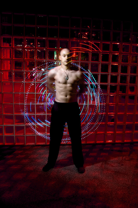
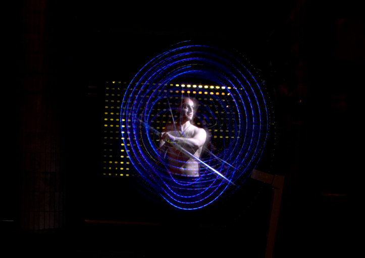
I've finally gotten around to getting some decent pictures of my glowstaff, mainly coz a friend wanted me in her magazine (Filament). Pics taken by Loki Gash:
Non-Https Image Link
Non-Https Image Link
Long exposures + LEDs FTW! (Microcontrollers without regulated power supplies FTL though.)
82 posts
Nice!
I like these a lot!
You play with fire,
You're going to get burned.
newbie
42 posts
Location: New Zealand
Hi All,
I've finally got around to writing up some details about building my glow staff, the Mitochondrion Mark 3.5. Lots of useful technical info if you're wanting to build one yourself, or at least lots of "I did it this way, it didn't work very well, you should do it a different way".
The writeup is in eight parts, I've the first four posted and the rest will be next week.
I'm now working away on the Mark 4.1 (amongst other projects), using an Arduino Nano as the brain, Adafruit's addressable RGB LED strips as the lights, twenty batteries for power, and numerous 3D printed parts to hold it all in place. It should be excessive.
old hand
1,174 posts
Location: Great Malvern [UK]
I'd not seen those LED strips before, but they look rather impressive. How far apart are the LEDs? They look like there's a reasonable gap in between?
How fast is the PWM loop now and what kind of resolution can you get (smallest period an LED can be programmed for)?
Looks fantastic - nice work!
Cake or Death?
newbie
42 posts
Location: New Zealand
Yeah, they're pretty sweet. The LEDs are 32 mm apart which is bearable, I know I can do LEDs closer, but then I'd have to spend the time making yet more kit.
PWM on them is a couple of megahertz, so sufficient. For the refresh rate, people using them for other projects have talked about being able to update the strip in under a millisecond (depending upon length), so the slowest part of my next set-up might be the Arduino as it generates patterns. Still, I won't know until I've got things working in hardware...
And cheers, it's been a labour of love and lots of work, with occasional swearing.
newbie
42 posts
Location: New Zealand
Ok, the whole writeup now is up at https://happyinmotion.livejournal.com/tag/mitochondrion.
Now I can get on with building the next generation...
EDITED_BY: happyinmotion (1321476329)
Unofficial Chairperson of Squirrel Defense League
4,061 posts
Location: South Africa
I remember this. Well cool.
'We're all mad here. I'm mad, you're mad." [said the Cat.]
"How do you know I'm mad?" said Alice.
"You must be," said the Cat, "Or you wouldn't have come here."
- Lewis Carroll, Alice's Adventures In Wonderland
2 posts
Link no longer works (I know it was a few years ago) - does anyone have a mirror?
Photos a few posts up look great. I just started looking into bojutsu.
I made my own LED staff but haven't gotten as far as making it programmable! 60 euros total you said?
I spent about $25 and posted instructions for how to make your own here:
uselesspuzzles.blogspot.com
would love to make it programmable for the next iteration... any advice would be helpful!
Non-Https Image Link
Non-Https Image Link
EDITED_BY: Triskite (1341411577)
© 1998 - 2024 Home of Poi

All prices converted to United States dollars using XE.com